boundary diagram
FedRAMP Authorization Boundary Guidance DOCUMENT REVISION HISTORY. Other none more business.
Fachbeitrage Blockdiagramm Fmea Boundary Diagramm Dietz Consultants
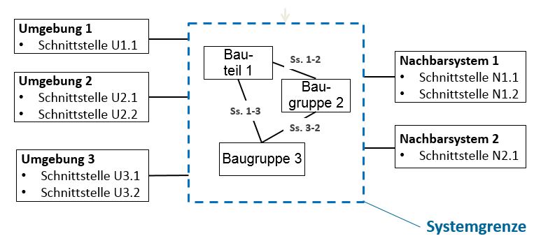
A boundary diagram is a graphical illustration of the relationships between the subsystems assemblies subassemblies and components within the object as well as the interfaces with.

. It also defines the most important external interfaces that must be considered. Select the shape and then drag a. An example of this type of convergent boundary is the Washington-Oregon coastline of the US.
Resize a System Boundary shape. Here the oceanic plate of Juan de Fuca is subducting beneath the North. Purpose Why Developing one or more boundary diagrams together with the responsible experts.
The Boundary Diagram Editor is used to create and customize Boundary Diagrams used to define the scope of work and critical interfaces for DFMEA in Relyence FMEA. For a suggested step. A boundary diagram defines the scope of system design or analysis to be included in the project charter.
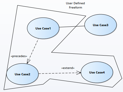
Note that default Relyence Block types cannot be deleted but their properties can be customized as needed. A system boundary is a rectangle that you can draw in a use-case diagram to separate the use cases that are internal to a system from the actors that are external to the system. System Boundary Diagram classic Use Createlys easy online diagram editor to edit this diagram collaborate with others and export results to multiple image formats.
Boundary Guidance Version 20 07132021 InfoFedRAMPgov FedRAMPgov. Authorization boundary diagrams should also show components or services that are controlled by your customer or those leveraged as an external service. In order to configure Interfaces andor Blocks for your DFMEA Boundary Diagrams.
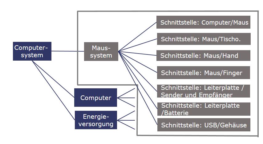
A boundary diagram represents all the interfaces of a system in the form of a block diagram. You can edit this. Net work and Data Flows.
Use Createlys easy online diagram editor to edit this diagram collaborate with others and export results to multiple image formats. Identify which systems sub-systems or components influence a product or process within the boundary of the teams. Boundary Diagrams can be used in product development processes to.
Boundary diagrams are part of the tools of every experienced FMEA moderator. The Authorization Boundary Diagram is a visual representation of the components that make up the authorization boundary by defining the authorization boundary for the CSO. In a use case diagram the system boundary is a boundary surrounding the use cases which indicates the system.
Copy of BOUNDARY DIAGRAM. It is the useful introduction to aFMEA as the functions of a system along with the failures are.
Model Boundary Diagram Download Scientific Diagram

Fmea Block Diagrams

Fmea Block Diagrams Boundary Diagrams
Professional Articles The Boundary Diagram Better System And Fmea Design With Block Diagrams Dietz Consultants

System Boundary Properties Enterprise Architect User Guide
System Boundary Properties Enterprise Architect User Guide

Etool System Boundary Diagram Etool
Boundary Enterprise Architect User Guide

Fmea Corner Making The Fmea Scope Visible

Engn2225 Oc System Boundary Chart Youtube
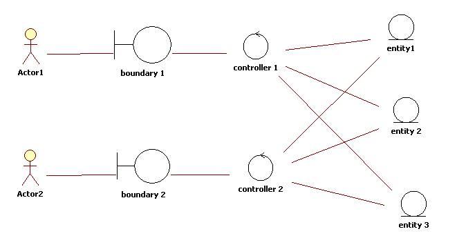
The Entity Control Boundary Pattern

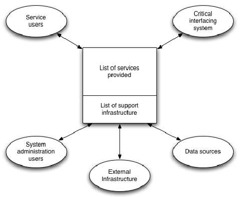
System Context Diagram Wikipedia
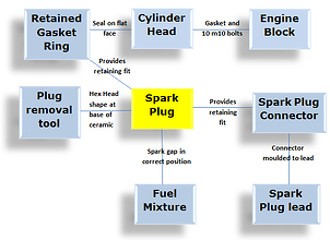
Boundary Diagram How To Construct An Fmea Boundary Diagram
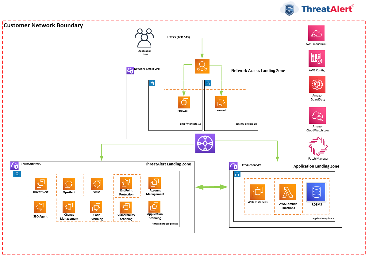
Dedicated Authorization Boundary Stackarmor

Communication Diagram Elements

Model Is Database A Controller Or Boundary In A Sequence Diagram Stack Overflow
File System Boundary Diagram Png Wikimedia Commons